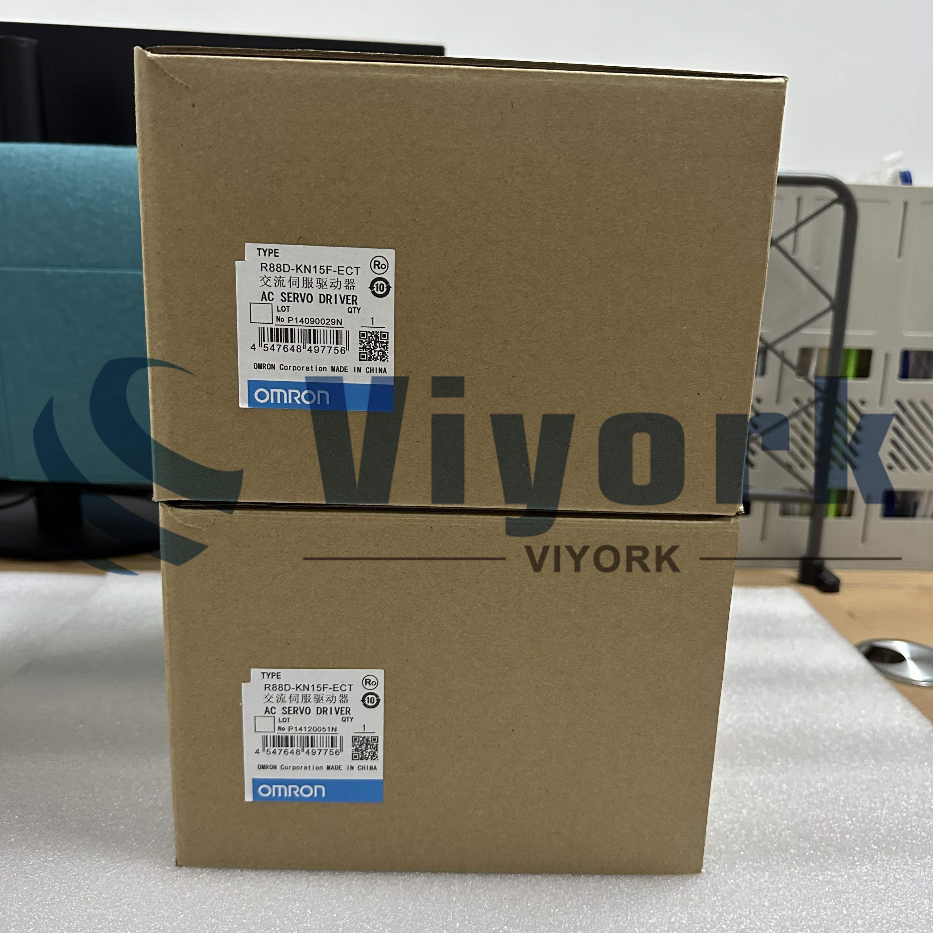
AC servo motor technology draws lessons from and applies the technology of frequency conversion. Based on DC motor servo control, it is realized by imitating the control method of DC motor through frequency conversion PWM method. That is to say. The AC servo motor must have frequency conversion. Frequency 50, 60HZ alternating current is first rectified into direct current. Then through various transistors (IGBT, IGCT, etc.), that can control the gate, the carrier frequency and PWM are adjusted to invert into an adjustable frequency waveform similar to the pulsating power sine and cosine. Because the frequency is adjustable, the speed of the AC motor can be adjusted (n=60f/p, n speed, f frequency, p pole pair number).
1. Different overload capacity
Servo drives generally have three times the overload capacity, which can be used to overcome the moment of inertia of the inertial load at the moment of starting. At the same time, the inverter generally allows 1.5 times the overload.
2. Different control accuracy
The control accuracy of the servo system is much higher than that of the frequency conversion. Usually, the control accuracy of the servo motor is guaranteed by the rotary encoder at the back of the motor shaft. The control accuracy of some servo systems can even reach 1:1000.
3. Different applications
Frequency conversion control and servo control are two control categories. The former belongs to the field of transmission control, and the latter belongs to the field of motion control. One is to meet general industrial applications' requirements and pursue low-cost applications where performance indicators are not high. The other is the pursuit of high precision, high performance, and high response.
4. Different acceleration and deceleration performance
Under no-load conditions, the servo motor is processed from a static state to 2000r/min, and the time will not exceed 20ms. The acceleration time of the motor is related to the inertia of the motor shaft and the load. Generally, the greater the inertia, the longer the acceleration time.
To put it simply, the working principle of the AB servo drive motor system is based on an open-loop controlled AC and DC motor and feedback. The speed and position signals are sent back to the servo drive through rotary encoders, resolvers, etc., for closed-loop negative feedback PID adjustment control.
Coupled with the current closed-loop inside the servo drive, the motor's output's accuracy and time response characteristics following the set value are greatly improved through these three closed-loop adjustments.
The AB servo motor system is a dynamic follow-up system, and the steady-state balance achieved is also a dynamic balance.
 Call us on:
  Email Us:
  1103, Block C, South Building, Luo Fang Road, Luohu District, Shenzhen, 518001, China


